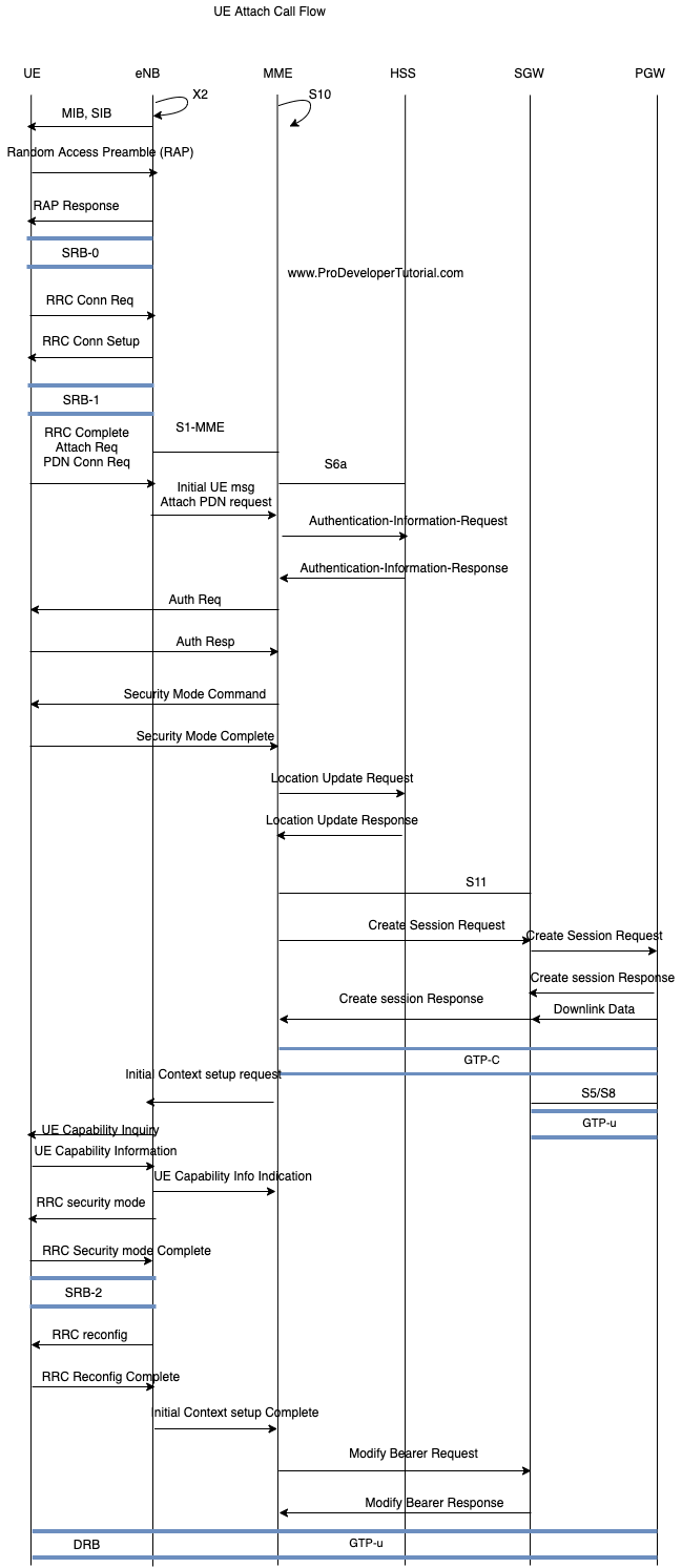
Step 1:
UE will read MIB and SIB from network to synchronize with the network.
Step 2:
UE will send Random Access Preamble (RAP) message to eNB to achieve uplink synchronization.
Step 3:
Random Access Preamble Response
Step 4:
RRC connection Request will be sent from UE to eNB which will have UE identity (S-TMSI = MMEC + M-TMSI) and establishment cause for RRC Connection request.
Step 5:
RRC Connection Setup: eNB will send DL-SCH message to UE to create a SRB. This message will have configuration parameter for RLC, UL-SCH, Power Head Room and Uplink Power Control.
Step 6:
UE will send RRC Connection Complete + Initiate Attach Procedure as NAS payload and PDN connectivity request.
Step 7:
Attach PDN Request
eNB will send the attach request to MME. This message will be sent via S1AP protocol and it will hve PDN connectivity request, TAI and E-UTRAN Cell Global Identifier (ECGI)
Step 8:
Authentication request and info:
MME will send authentication request to HSS, it will have K-ASME, XRES and RAND.
Step 9:
Authentication Response:
UE will send the authentication response value which was computer from the K key, AUTN and RAND
Step 10:
Security Mode Complete:
MME will send the encryption and integrity protection algorithm and key selection identifier (KSI-ASME). The UE will respond back to MME with NAS ciphering and integrity protection.
Step 11:
Location Update Request:
Step 12:
Session Request:
Create session request message will be sent from MME to SGW too create a GTP tunnel.
Step 13:
Create default bearer request:
SGW will send create default bearer request to PDN-GW to create a EPS bearer and generate a charging ID.
Step 14:
Default bearer response:
PDN-GW will send this response message to SGW.
Step 15:
Session Response:
This message will be sent form SGW to MME to indicate establishment of GPRS Tunneling Protocol for control (GTP-C) tunnel.
Step 16:
Initial context setup request:
MME will send eNB with NAS attach accept and activate default bearer request.
Step 17:
RRC security mode
eNB will send RRC security mode message with the AS integrity protection and encryption algorithms. UE will send ack message that uses the newly activated keys to encrypt and integrity protection.
Step 18:
RRC re-config
eNB will send to UE, RRC Reconfig message to activate default radio bearer.
Step 19:
RRC Complete:
UE will send eNB RRC complete message.
Step 20:
Data flow.