SSB stands for stands for Synchronization Signal Block.
It is commonly referred as Synchronization/PBCH block as it has Synchronization and PBCH channel.
So a SSB has:
1. Synchronization Signal : PSS (Primary Synchronization Signal), SSS (Secondary Synchronization Signal)
2. PBCH : PBCH DMRS and PBCH (Data)
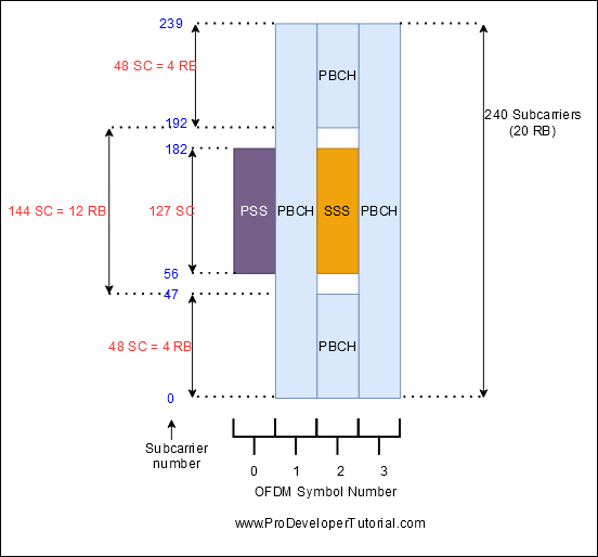
SSB is transmitted in 4 OFDM symbols in time domain and 240 sub carriers in frequency domain.
In 4-SSB-symbol, 1-symbol PSS, a 1-symbol SSS, and a 2-symbol PBCH.
PSS occupies first OFDM symbol and span over 127 sub carriers.
SSS is located in the third OFDM symbol and span over 127 sub carriers.
PBCH occupies two full OFDM symbols (second and fourth) spanning 240 subcarriers and in the third OFDM symbol spanning 48 subcarriers below and above SSS totaling to 240+48+48+240 = 576.
In that PBCH DM-RS occupies 144 REs which is one-fourth of total REs and remaining for PBCH payload (576-144 = 432 REs).
With the help of SS, UE can obtain the Physical Cell Identity (PCI), achieve downlink synchronization both time and frequency domain, and acquire the timing for PBCH. PBCH carries the very basic system information.
Below image is of a SS Block:
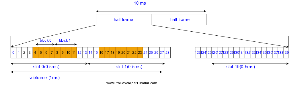
SSB details in Time Domain:
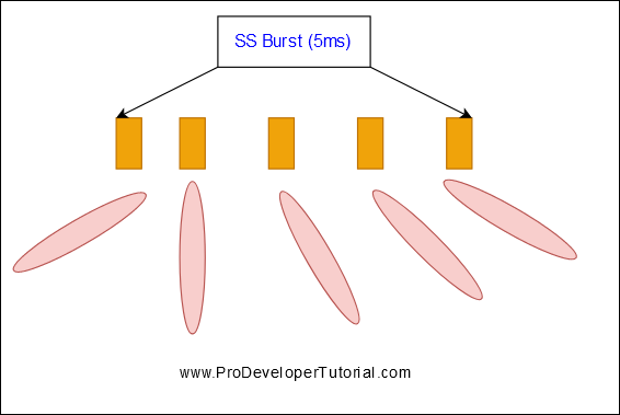
Collection of SSB transmitted in a batch is called as SS Burst. Collection of SS Burst is called as SS Burst Set.
It will send in pre-defined bursts across the time domain. The bursts periodicity depends of the time slots according to the numerology defined.
The default transmission periodicity is 20ms for all frequency range but can be set between 5, 10, 20, 40, 80 160 ms.
Longer SSB periodicity enhances network energy performance and the shorter periodicity facilitates faster cell search for UEs.
During this time, number of SS Blocks will be transmitted in different directions called as Beams during a 5ms Period.
An SS Burst Set is always confined to a 5ms window and is either located in first-half or in the 2nd half of a 10ms radio frame.
The network sets the SSB periodicity via RRC parameter ssb-PeriodicityServingCell which can take values in the range {5ms, 10ms, 20ms, 40ms, 80ms, 160ms}.
Within this 5ms window, number of possible candidate SS block location is L.
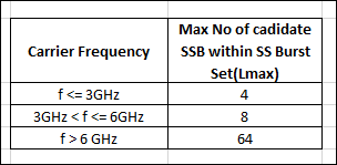
The maximum number of candidate SSBs (Lmax) within an SS burst set upon carrier frequency as shown below:
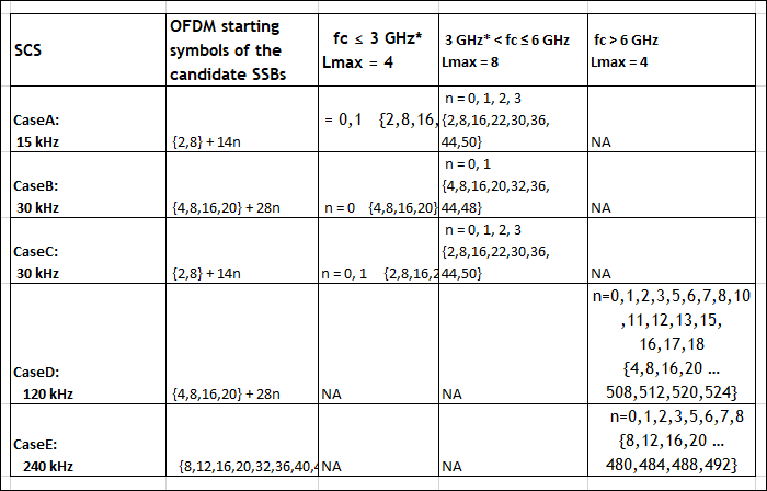
In a 5ms half frame, the OFDM symbol index for a candidate SSB within a SS burst depends on SCS and frequency/band:
Let us understand with help of an example:
Example 1:
Subcarrier spacing = 50 KHz , carrier frequency < 3 GHz (Case A)
n = 0,1
Symbol Index = {2,8}+14*n
For n =0,symbol index = {2,8}+14*0 = {2,8}
For n =1 ,symbol index = {2,8}+14*1 = {2+14*1 ,8+14*1} = {16,22}
Total number of index (L)= 4 and symbol index set = {2,8,16,22}
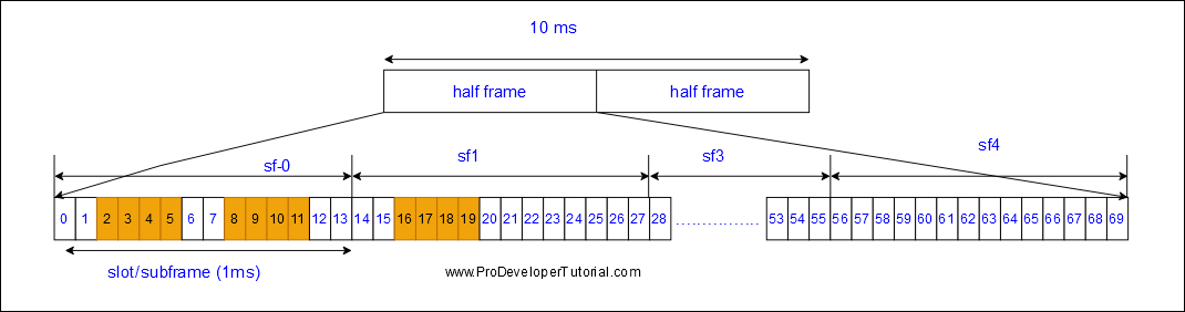
From above image we can see there are 4 SS/PBCH blocks in half frame with starting indexes 2,8,16,22 for case A.
Example 2:
Subcarrier spacing = 30 KHz , 3 GHz<carrier frequency < = 6GHz (Case B)
n = 0,1 ; symbol index = {4,8,16,20}+28*n
For n =0 , symbol index = {4+28*0,8+28*0,16+28*0,20+28*0} = {4,8,16,20}
For n =1 , symbol index = {4+28*1,8+28*1,16+28*1,20+28*1} = {32,36,44,48}
Total number of index(L) = 8 and symbol index set = {4,8,16,20,32,36,44,48}
SS Burst:
A set of SS block is called as SS Burst in a half subframe.
In the 2nd example, there are 8 ss block (4,8,16,20,32,36,44,48) in a half frame, this is called as SS Burst.
Each SS blocks in a SS Burst will be for different beam.
SIB-1 parameter “ssb-PositionsInBurst” informs the domain position of SS Block in the SS Burst.
Read more at 3GPP 38 211 5G; NR; Physical Channels and Modulation