As we discussed in previous chapter, handover is based on 3 steps as below:
1. HO Preparation
2. HO Execution
3. HO Completion
1. HO preparation
Consider the image below
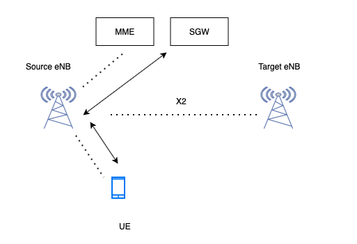
We have 2 eNB, source eNB and Target eNB. We have MME and SGW. SGW is connected to PGW.
Both source eNB and target eNB are connected to each other with help of X2 interface.
UE is attached to source eNB. Signaling (dotted line) is shared between UE <-> eNB <-> MME and data (solid line) is shared between UE <-> eNB <-> SGW.
During initial attach request, eNB will send “RRCConnectionReconfiguration” request. It will have measObjectId, reportConfigId (A1, A2…). Based on these configuration, UE will make the decision.
Step 1:
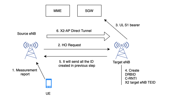
Now, UE will move towards Target eNB, then UE will send measurement report to source eNB. It will include “rsrpResult” and “rsrqResult”.
Step 2:
Source eNB will send a “HandoverRequest” message to TargeteNB.
It will have target eNB cellID, details of ERAB (QCI, ARP, S1 SGW TEID (UL)) to be established.
Now Target eNB will receive S1 SGWTEID.
Step 3:
As source eNB is sharing “S1 SGWTEID”, target eNB will make a uplink bearer to SGW with the help of “S1 SGWTEID”. Now only UL has been established from Target eNB to SGW. But till now downlink is not established.
Step 4:
Target eNB will create “DRB ID”, “C-RNTI: Identifier for UE in a cell”, “X2 Target eNB TEID”.
These 2 details will be shared to source eNB and then source eNB will share to UE.
Step 5:
Target eNB will send HO Req ACK. It will send all the ID’s created in previous step.
Step 6:
Now source eNB will create a bearer towards target eNB. It is called as X2AP direct tunnel.
This is because, the source eNB can forward packets received from SGW to target eNB.
Below image gives high level idea of steps performed during HO preparation.
2. HO Execution
Step 1:
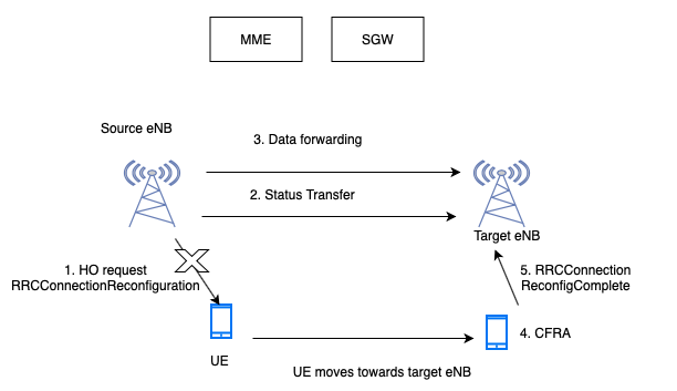
HO command. Here source eNB will send “RRC Connection Reconfiguration” to UE.
In this request, “DRB-ID” and “C-RNTI” will be shared to UE. These 2 ID’s will be generated by target eNB.
Step 2:
Source eNB will send “Status Transfer” message to target eNB.
It will have “DL Count” and “UL Count”.
Step 3:
Now “Data forwarding” will occur. It means, the DL packets coming from SGW to source eNB, will be forwarded to “target eNB” through direct tunnel.
Because there will be no radio interface between “source eNB” and “UE”.
But “target eNB” has not established radio interface with UE to forward the packets.
So “target eNB” will buffer the packets.
Step 4:
Now suppose, UE is in the coverage of “target eNB”. Target eNB will send a “Contention Free Random Access(CFRA)”.
Step 5:
UE will send “RRC Connection Reconfiguration Complete”. HO Confirm.
In this case, UE will send UL packets to “target eNB” and “target eNB” will forward to SGW.
Still DL packets follow “SGW -> source eNB -> target eNB -> UE”
As HO is confirmed, buffering will not take place.
Packets will be forwarded to UE.
This completes HO Execution.
3. HO Completion
So till now the data flow is like below:
DL packets follow “SGW -> source eNB -> target eNB -> UE”
UL packets follow “UE -> target eNB -> SGW”.
Step 1:
“target eNB (t eNB” will send “PATH SWITCH REQUEST” to MME. It will include “S1 TeNB TEID(DL)”.
Step 2:
MME will send “Modify Bearer Request” to SGW. “S1 TeNB TEID(DL)” ID will be sent to SGW.
Step 3:
SGW will create a DL bearer.
Step 4:
“Modify Bearer Response” from SGW to MME.
Step 5:
“End marker” packet to source eNB from SGW.
This “End marker” packet will be forwarded from source eNB to target eNB.
Step 6:
“PATH SWITCH REQUEST ACKNOWLEDGE” from MME to target eNB.
Step 7:
“UE CONTEXT RELEASE” from target eNB to source eNB.
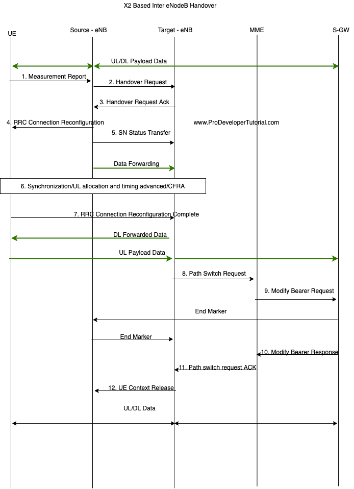
Full call flow of X2 Handover is as shown below: