In the previous chapter we saw X2 based inter eNB HO.
In this chapter we shall learn S1 based HO.
Scenarios where we need S1 HO.
1. If X2 interface is busy to perform HO.
2. If X2 interface is not present in between 2 eNB.
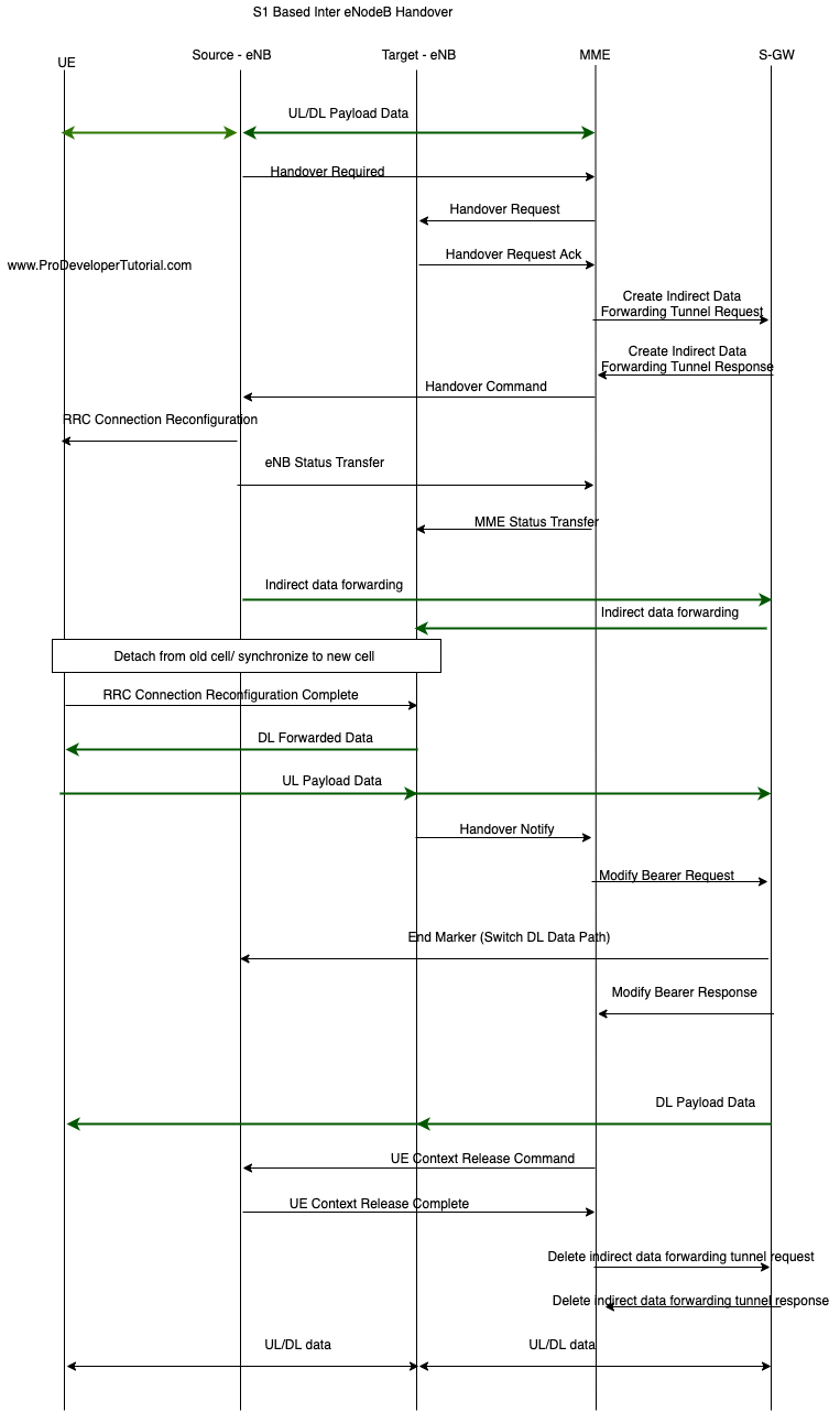
This handover is based on 3 steps as below:
1. HO Preparation
2. HO Execution
3. HO Completion

1. HO Preparation
Step 1:
Some thresholds will be met and UE will send Measurement report. It will include “rsrpResult” and “rsrqResult”.
Source eNB will decide if HO should happen or not.
Here source eNB will not talk to target eNB because of lack of X2 interface.
Hence source eNB will talk with MME and MME will talk with target eNB.
Step 2:
HO Required from source eNB to MME.
It will include “ERAB to be established: QCI, ARP, AMBR related info, target-eNB ID, S1 SGW TEID”
Step 3:
“HANDOVER REQUEST” from MME to Target eNB.
It will include “ERAB to be established: QCI, ARP, AMBR related info, target-eNB ID”
Step 4:
Target eNB will receive “S1 SGWTEID (a)”, now t-eNB will be able to send packet to SGW.
It will create “S1 t-eNBTEID (b)”, “s1 t-eNBTEID (c)”, allocate DRB ID and CRNTI
Step 5:
“HANDOVER REQUEST ACKNOWLEDGE” from Target eNB to MME. It will include above ID’s crated by t-eNB.
Step 6:
Create Indirect Data Forwarding Tunnel Request, MME -> SGW. It will send “S1 t-eNBTEID (b)”
Step 7:
Create Indirect Data Forwarding Tunnel Response, SGW -> MME. It will receive “S1 t-eNBTEID (b)”, it will create a tunnel towards t-eNB.
It will also create “S1 SGWTEID (d)” and send it to MME.
Step 8:
“HANDOVER COMMAND” MME -> source eNB. It will include “DRB, CRNTI, S1 SGWTEID (d)”.
Now s-eNB will create a bearer towards SGW.
Now “s-eNB -> SGW -> t-eNB” path is established.
2. HO Execution
Step 1:
“RRCConnectionReconfiguration” from “source-eNB (s-eNB)” to “UE”. Now there is no connection between UE and s-eNB.
Step 2:
“eNB STATUS TRANSFER” from “s-eNB” to “MME”. It will have UL/DL count.
It helps to know from which packet number t-eNB should send to UE.
Step 3:
“MME STATUS TRANSFER” from MME to t-eNB.
Step 4:
Now there will be indirect data transfer as
“SGW -> s-eNB -> t-eNB -> SGW -> t-eNB -> buffer”
Step 5:
Detach from old cell/Synchronize to new cell
Step 6:
“RRCConnectionReconfigurationComplete” UE -> -eNB.
Now DRB will be established from UE to t-eNB.
UL is already established.
But downlink will take a long path “SGW -> s-eNB -> t-eNB -> SGW -> t-eNB -> buffer”.
This will be taken in HO complete.
3. HO Completion
Step 1:
“HANDOVER NOTIFY” t-eNB to MME.
Step 2:
“Modify Bearer Request” from MME to SGW
Step 3:
“Modify Bearer Response” from SGW to MME
Step 4:
“End marker” from SGW to s-eNB.
Step 5:
“End marker” from s-eNB to t-eNB