Once the Random access procedure is completed, the next step is to RRC connection establishment procedure.
This procedure will change the state of RRC from RRC_IDLE to RC_Connected.
UE must change the state from RRC Idle to RRC Connected before it can transfer any application data or signaling procedures.
RRC Connection Establishment can be triggered by UE or by network.
If the application needs to send a message, then it can trigger. Or UE can trigger if it moves to a new Tracking Area and has to complete Tracking Area Update signaling procedure.
Network can trigger by sending a Paging message. After a paging message has been sent by eNB, then RRC Connection setup request will be sent by the UE.
RRC Connection Establishment Procedure is used to configure SRB1.
RRC Connection Establishment Procedure is a 3 way handshake procedure. It has below 3 messages.
RRC connection Request
RRC connection Setup
RRC Connection Setup Complete
RRCConnectionReject
RRC Connection Establishment:
RRC Connection Establishment is a part of Random Access Procedure.
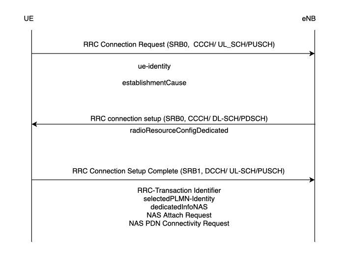
As shown in the diagram, for RRC Connection Request, it includes a UE Identity and and establishment cause.
The UE identity is signalled using the SAE Temporary Mobile Subscriber Identity (S-TMSI).
The establishment cause can be any of the below, and it is determined by NAS procedure for which the connection is being established.
Emergency
High Priority Access
Mobile Terminating Access
Mobile Originating Signalling
Mobile Originating Data
T300 timer will be started. Upon expiry of this timer UE goes to RRC_IDLE mode. It can be set to 400, 600, 800, 1000, 1200, 1400, 1600, 1800, 2000, 3000, 4000, 6000, 8000 ms.
RRC connection Request
Direction UE to eNB
SRB0
RLC Mode: TM
Logical Channel: CCCH
Transport Channel: UL-SCH
RRC connection request is used to establish an RRC Connection.
IE’s in RRCConnectionRequest message:
RRCConnectionRequest-r8-IEs ::= SEQUENCE{
ue-Identity
establishmentCause
spare
}
Information Elements in RRC Connection Request are:
ue-Identity: It can be either S-TMSI(40-bits) from upper layer or a bit of randomValue(40-bits). If the UE is registered in TA of current cell, then upper layers can send S-TMSI number.
establishmentCause:
emergency: Corresponding NAS procedure “MO-CS fallback Emergency Call”
mt-access [mobile terminated access]: Corresponding NAS procedure “Service Request” or “Extended service Request”
mo-signalling [mobile originating signalling]: Corresponding NAS procedure “Attach, Detach and TAU”
mo-Data [mobile originating data]: Corresponding NAS procedure are “Service Request” and “Extended Service Request”
RRC connection Setup:
Direction eNB to UE
SRB0
RLC Mode: TM
Logical Channel: CCCH
Transport Channel: DL-SCH
If the eNB allows network access, then it will send this message to UE.
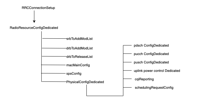
This message will have the configuration details for SRB1. Along with that it will have configuration for SRB, DRB, MAC and PHY.
It will also include the configuration for
PUSCH
PUCCH
PDSCH physical channels
CQI Reports
Sounding reference signal
antenna configuration
scheduling requests
Uplink Power control
UE enters into RRC Connected state and stops cell reselection procedure
UE will stop T300 Timer.
IE’s RRCConnectionSetup message
RRCConnectionSetup-r8-IEs ::= SEQUENCE{
radioResourceConfigDedicated
nonCriticalExtension
}
radioResourceConfigDedicated will have below IE’s
RRC Connection Setup Complete:
Direction UE to eNB
SRB1
RLC Mode: AM
Logical Channel: DCCH
Transport Channel: UL-SCH
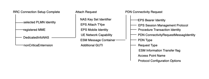
RRC Connection Setup Complete is used to confirm the successful completion of RRC connection establishment.
In this message, Information Elements are:
Selected PLMN identity(1 to 6)
Registered MME
NAS information
IE’s in RRC Connection Setup Complete Message:
RRCConnectionSetupComplete-r8-IEs ::= SEQUENCE {
selectedPLMN-Identity
registeredMME
dedicatedInfoNAS
nonCriticalExtension
}
Explanation of the IE’s
selectedPLMN-Identity:
Index of the PLMN selected by the UE from the plmn-IdentityList included in SIB1. 1 if the 1st PLMN is selected from the plmn-IdentityList included in SIB1, 2 if the 2nd PLMN is selected from the plmn-IdentityList included in SIB1 and so on.
registeredMME:
This field is used to transfer the GUMMEI of the MME where the UE is registered, as provided by upper layers.
dedicatedInfoNAS:
This IE includes the initial NAS message from the UE
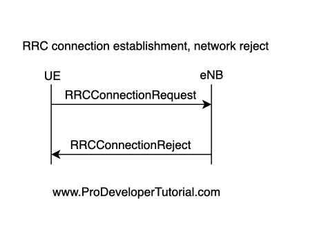
RRC Connection Reject
The RRCConnectionReject message is used to reject the RRC connection establishment.
Signalling radio bearer: SRB0
RLC-SAP: TM
Logical channel: CCCH
Direction: E-UTRAN to UE
Transport Channel: DL-SCH
IE’s RRCConnectionReject message:
RRCConnectionReject-r8-IEs ::= SEQUENCE{
waitTime
nonCriticalExtension
}
As you can see, “waitTime” IE is used that ranges from 0 to 16.
Upon Reception of the RRCConnectionReject by the UE, UE will:
* stop timer T300;
* start timer T302, with the timer value set to the waitTime;
* UE should not send another RRCConnectionRequest for mobile originating calls, mobile originating signalling, mobile terminating access and mobile originating CS fallback on the same cell on which RRC CONNECTION REJECT is received until the expiry of T302
Reference: 3GPP TS 36.331