In this chapter we shall see Radio Link Control layer in detail.
Before that we shall see an example of Data Flow:
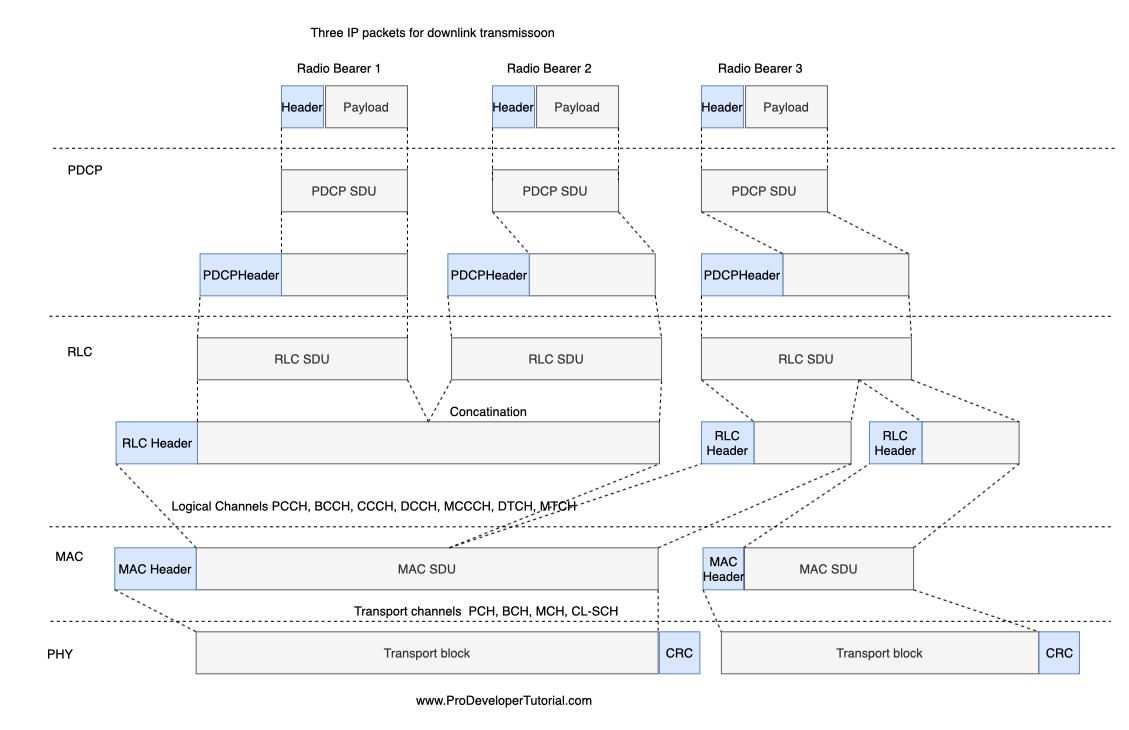
SDU: Packets received by a layer are called Service Data Unit
PDU: Packet output of a layer is referred to by Protocol Data Unit
Introduction to RLC Layer
1. The layer above of RLC layer is PDCP layer and the layer below to RLC is MAC layer.
2. WKT PDCP layer will perform cyphering and integrity protection. For some of the messages which does not need cyphering and integrity protection will bypass PDCP layer and messages will directly go to RLC layer. So in this case the layer above RLC layer will be RRC layer.
3. RRC messages transmitting on CCCH, BCCH, PCCH does not need any security protection, so they will skip PDCP and directly reaches to RLC layer.
Below are the functions of RLC:
1. Transfer of upper layer PDU [Packet Data Unit]
2. Error correction through ARQ
3. Concatenation, segmentation and reassembly
4. RLC re-establishment
5. Duplicate detection
Below are 3 major functionality of RLC layer:
1. Three types of RLC Mode : TM Data Transfer, UM Data Transfer, AM Data Transfer
2. Segmentation (Splitting) and Concatenation (Combining) mechanism
3. RLC Timers
RLC structure.
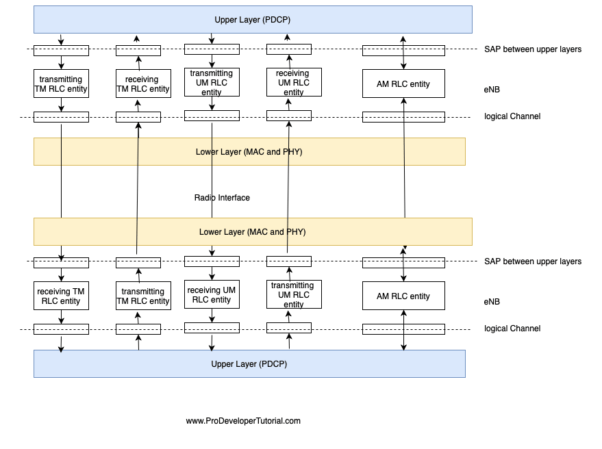
From the above image we can see that there are 3 entities.
1. TM Data Transfer: Transparent Mode
2. UM Data Transfer: Un Acknowledgment Mode
3. AM Data Transfer: Acknowledgment Mode
Here the Upper layer for RLC is PDCP.
The Bottom layer for RLC is Mac and PHY.
RLC Downlink Data Flow:
———————————————–

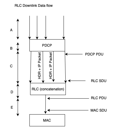
Form the image we can infer that:
A. IP packets from eNB is coming to PDCP.
B. PDCP will add PDCP header and sends to RLC
C. PDCP packets coming to RLC
D. RLC will concatenate multiple SDU into huge packets and adds RLC header
E. Concatenated RLC packet PDU is forwarded to MAC layer.
RLC UpLink Data flow:
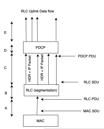
Form the image we can infer that:
A. MAC receives huge IP packets and forwards to RLC.
B. RLC will split the packets into multiple SDU. RLC header is removed.
C. RLC SDU will be forwarded to PDCP
D. Packets coming to PDCP, PDCP header is removed
E. Stripped PDCP packets are individual IP packets.
The need for 3 transfer modes in RLC?
According to the data rate, 3 different data transfers are available.
RLC Data Transfer mode 1: TM mode

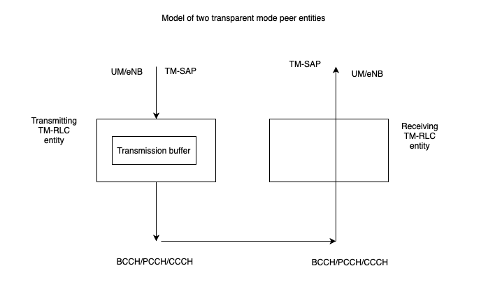
It is one of the simplest RLC mode.
TM stands for Transparent mode.
No retransmission, no segmentation/reassembly.
This configuration is used for broadcast channels BCCH, CCCH, PCCH
RLC Data Transfer mode 2: UM Mode

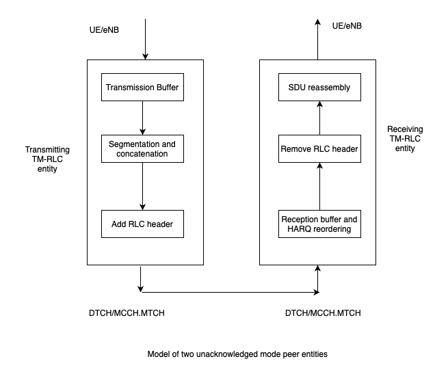
UM stands for Unacknowledged Mode.
It means it will not require any ACK/NACK.
Segmentation and reassemble
In sequence delivery
No retransmission
On the transmitting side:
i) Buffering
ii) Segmetation
iii) Concatenation
iv) Add RLC header
On the receiving side:
i) Buffering
ii) Reordering
iii) Remove the RLC header
iv) Reassembly
RLC Data Transfer mode 3: AM Mode
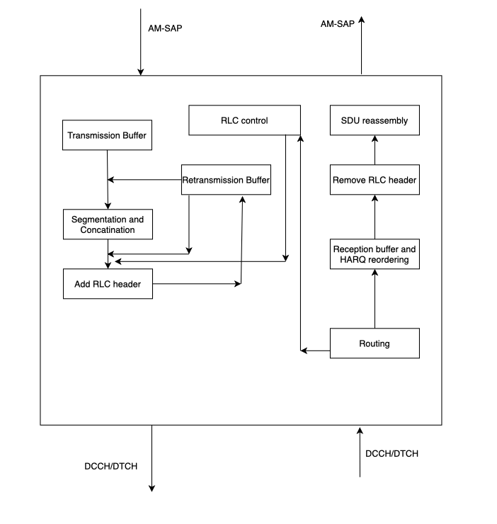
AM stands for Acknowledge Mode
It is most complex mode of all the 3 modes.
It requires ACK/NACK from other party.
As it is expecting ACK/NACK for every transmission, it will have much overhead.
The left and right side of the diagram, the procedure is same as UM mode.
The only difference is the “Retransmission Buffer” and “RLC control” procedure.
Below is how “Retransmission Buffer” will work:
1. When the segmentation/concatenation process and adding of RLC header is completed, the same message is transmitted to MAc and Retransmission Buffer.
2. If the RLC did not receive any response or it received NACK, then RLC packet in the retransmission buffer will get transmitted again.
RLC Segmentation and concatenation
As we saw in the data flow image above,
1. Multiple RLC SDU are segmented and concatenated into a single RLC PDU [from the lte data flow PDCP SDU when comes to RLC, it will become RLC SDU]
2. RLC SDU can be control information or voice or data
3. Mac knows what physical resource is available from physical, RLC will provide RLC PDU that the mac requests.
RLC AM PDU frame structure:

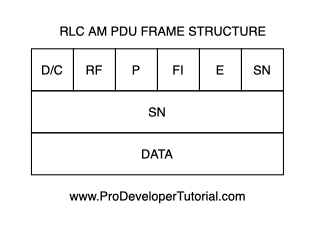
Here:
D/C: Data or control PDU
RF: RE-segmentation flag. It will indicate either a PDU or a PDU segment
p : Polling bit
FI: Framing Info.
SN: Segment Number
E: Extension Bit
LI: Length Indicator
If there are odd number of LI fields, then there will be 4 bits of padding
If there are even number if LI fields, then the padding is not required.
SN is 5 or 10 bits configurable for UM PDU
SN is 10 bits for AM PDU
FI:
00 – First byte of the data field corresponds to the first byte of a RLC SDU.
Last byte of the data field corresponds to the last byte of a RLC SDU.
01 – First byte of the data field corresponds to the first byte of a RLC SDU.
Last byte of the data field does not corresponds to the last byte of a RLC SDU.
10 – First byte of the data field does not corresponds to the first byte of a RLC SDU.
Last byte of the data field corresponds to the last byte of a RLC SDU.
11 – First byte of the data field does not corresponds to the first byte of a RLC SDU.
Last byte of the data field does not corresponds to the last byte of a RLC SDU.