On a high level, LTE architecture consists of 2 parts:
1. Radio Access Network: Evolved UTRA Network (E-UTRAN)
2. Core Network Architecture: Evolved Packet Core (EPC)
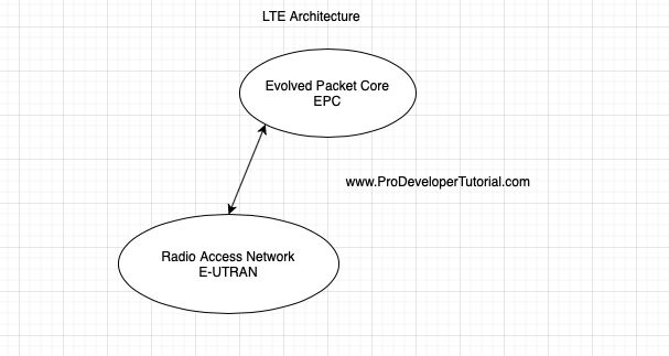
Both EPC [EPC is core network architecture] and E-UTRAN work together to give LTE service for a given subscriber.
More in-depth architecture is as below
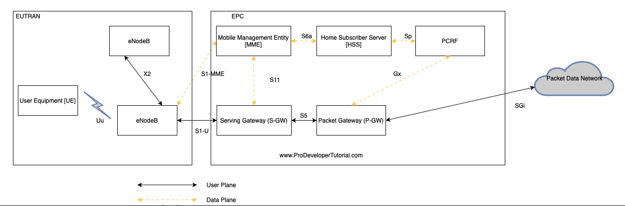
The above diagram gives detailed LTE architecture. Below we shall explore how they interact with each other.
- On the left side rectangle we have a “E-UTRAN” and on the right side we have “EPC”.
- In “E-UTRAN” as you can see we can have multiple “eNodeB” that communicate with each other.
Then we have a mobile phone or “User Equipment [UE]” that communicates with “eNodeB”.
Further “eNodeB” is connected to “EPC” entity called as “Mobility Management Entity [MME]”, “MME” is connected to “Home Subscriber Server [HSS]”, then “HSS” is connected to “PCRF”. “PCRF” stands for “Policy and Charging Rules Function”.
“MME” is also connected to “Serving Gateway [S-GW]”, “S-GW” is connected to network element “Packet Gateway [P-GW]”.
Now the “P-GW” is connected to “PCRF” and also to the “Packet Data Network”. “Packet Data Network” is the outside of EPC network.
“Packet Data Network” may consist of IP networks such as IMS, Internet, Apps.
Here solid line represents User Plane and dotted line represents Control Plane.
Now what is user plane and control plane?
On a high level, User Plane is used for handling the traffic like Data and Voice.
Control Plane is used for handling signaling between the nodes.
For example:
If the user wants to open “www.ProDeveloperTutorial.com”, before the actual web page is delivered to you, there are many background process like user authentication, user data validity, user data limit etc to be checked for.
All those process will taken care by control plane, once all the validation has been completed and other functions has been completed, actual web page that is being delivered to you, will be taken care by user plane.
Control Plane is also called as Signaling. In the image above, the bottom half is user plane traffic and above half is control plane.
Evolution of Network Services:
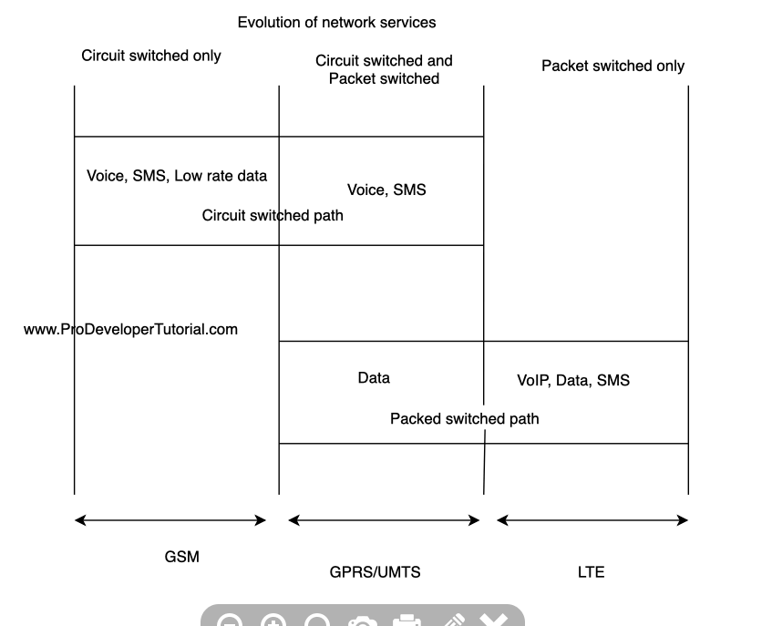
As you can see form the above image,
Initially in GSM everything was in Circuit Switched network.
As, the data consumption in the user increased, we moved towards “UMTS”, where the data has been converted into packet switched and Voice and SMS were still in circuit switched.
Now, in LTE everything is in Packet Switched.
Evolution of 3gpp architecture:
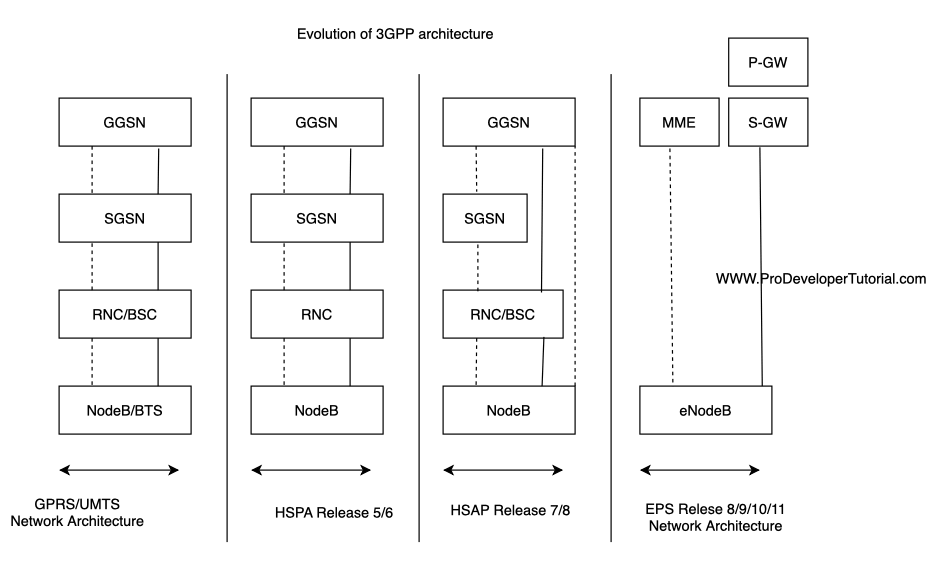
Currently we are referring to Release 8/9/10/11.
Again dotted line is control plane and solid line is user plane.
Note:
In the next chapter we shall see in brief working of all the network elements.