Below diagram shows the architecture of AIR interface:
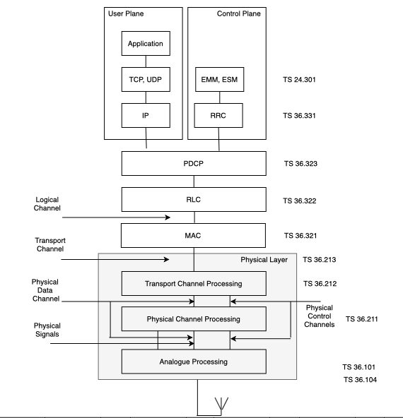
The above image shows the protocols used in the air interface with User Equipment Perspective
1. In the user plane as a transmitter, the application creates data packets and are processed by the protocols like UDP, TCP and IP.
2. In the control plane as a transmitter, Radio Resource Control (RRC) protocol writes the signaling message that are exchanged between BS and mobile.
3. Next all the information from the above layers will be processed by below layers:
* PDCP – Packet Data Convergence Protocol
* RLC – Radio Link Control Protocol
* MAC – Medium Access Control Protocol
4. Physical Layer has 3 parts:
4.1: Transport Channel Processor: It will apply error management procedures.
4.2 Physical Channel Processor: It will apply the techniques of OFDMA, SC-FDMA and multiple antenna transmission.
4.3 Analogue Processor: Converts the information to analogue form and mixes it up to radio frequency for transmission.
Channels in LTE:
The information flow between different protocols are known as channels and signals.
Below are different channels;
1. Logical Channels: It is the channel between RLC and MAC
2. Transport Channels : It is the channel between MAC and physical layer
3. Physical Data channels : It is the channel betweem different levels of the physical layer.